Aspect Ratio
Not long ago I read a conversation on the Professional Pilots’ Rumour Network which included “What does aspect ratio mean? What does it do?”, and “Span loading; I’ve no idea what this is. Any ideas…?”
What does aspect ratio mean?
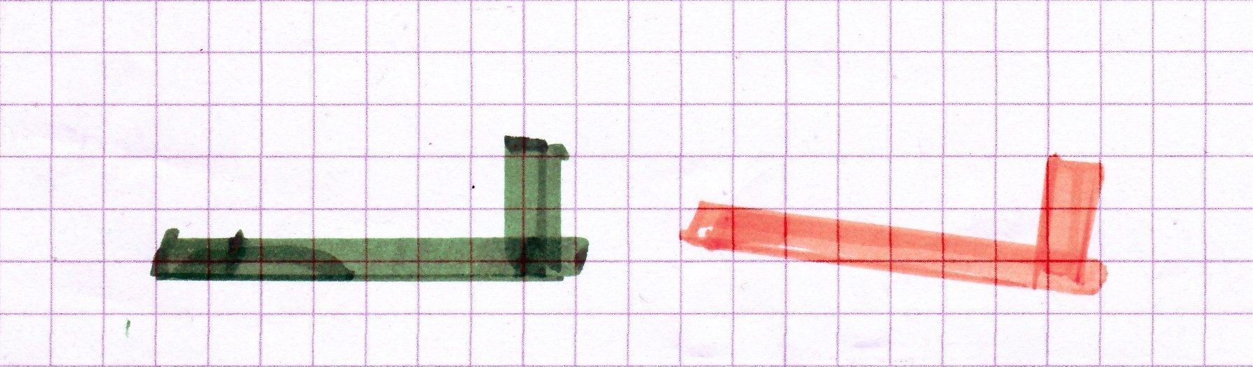
‘Aspect’ means what does it look like, and the Ratio part is a comparison of the length and width of the chosen wing shape (span and chord in aerospeak). A’s wing measures 12 by 2 metres - AR 6, while its chunkier friend B comes out at 8 by 3 - AR 2⅔.
They both have the same 24 sq. m. wing area, and we shall assume the same weight and general characteristics. So the wing loading is also the same, but what’s different about the way they fly, and how does this work?
If you want structural strength, roll rate and general throw-around convenience perhaps you should choose B, but many readers are interested in cheap travel, so transport efficiency and how to save the planet will be considered here. The simple truth is that A will get you to your destination using less fuel than B. If they are gliders A will very likely go further than B, and do it with fewer climbs so probably will arrive sooner.
How it works
The green example A processes 24 sq. m. of air each time it travels 2 metres, B has to travel 3 metres to work on the same 24 sq. m. of air.

What can B do about this when it flies at the same speed as A, in other words how can B compensate for this slower use of its wing area? Answer: take a deeper bite of the air as it travels along, in other words arrange for its wing to assume a larger angle of attack.
How does a wing generate the lift force required to counteract its aircraft’s weight?
Isaac Newton had already come up with an answer, 350 years ago, and perhaps he was not the first. His 3 basic rules of motion tell you all you need to know. Here’s rule 2 (momentum and force) with rule 3 (equal and opposite force reaction).
*As a working wing goes though the air it pushes a suitable mass of it (m) downwards at a suitable rate (v), resulting in a force (f) which includes the required upward force (lift) to counter the aircraft weight. *f=mv.

Woolsthorpe Manor
This is the Newton family farm, near the A1 midway between Grantham and Stamford. in 1665 a 22 year old Newton was a student at Trinity, Cambridge. That year the plague reached Cambridge, and Newton returned home as a safer place for his lockdown. Deprived of social networking or life-enhancing television advertisements he continued his studies.
Considering an apple fall from this tree one evening he wondered why the moon did not do the same thing, then realised that it did - but in a continuous circular track.
*Heresy Alert!
The Newton summary above appears to fly in the face of more than a century of ‘pressure distribution here and there around a wing section’ teaching tradition. Any boy who has toyed with a flat wing chuck glider understands how well it flies - just by pushing the air down. As Newton might have said, “This isn’t whole story, but there are several ways to skin a cat. I consider the basics first.”
Heresy Police
Early researchers, long before 1903, tried curving this flat wing to improve its capabilities, and the search for better performance and handling developed into the very sophisticated craft of wing profile design - well established and documented by the mid 1930s. We shall not trouble ourselves with this black art. It’s for aerodynamicists and designers, rather than the clear-minded action men of the real skies.
To fly level at the same speed as A, B must process the same mass of air per second as A. B’s shorter span means it must take a deeper bite of air as it goes along, in other words a larger angle of attack is required. B must work harder to lift the same weight.
What the wing does

Wing Working Force A
The wing provides the upward force for supporting the aircraft, but this force also has to lean back a bit. Lift is defined as its component at right angles to the flightpath - i.e. vertical in the case of level flight - and lift’s horizontal colleague is the drag caused by generating lift - lifting drag; for that’s what it is: a backwards force due to the production of lift.

Wing Working Force B
To fly at the same speed as A, B’s wing needs a greater angle of attack. Its wing’s working force has to lean back a bit more than A, and in providing the same vertical component to carry the same weight it also has to provide more working force than A - its lifting (induced) drag component is higher.
That’s Aspect Ratio in a nutshell, but here’s more.
What about the vortices?

Wingtip Vortices
This is a nice clear picture from Wikipedia. There are many such, and this one has a confident statement of truth, perhaps a correct multi-choice answer.
It could refer to glider A and Piper Cherokee B, but it indicates the symptom, and misses out the basic reason which A and B have explained above.
During the 5 straight-wing decades from 1900s-1950s wingtip vortex generation was accepted as a natural symptom of induced drag. Early swept wing handling behaviour then required wing fences and notched leading edges to create flow-stabilising extra vortices, and today interest in stylish sculptures on airliner wingtips now indicates the industry’s preoccupation with the life and death struggle of competitive fuel economy. What do these things actually do besides making a gismo statement? They interrupt the otherwise unopposed, vortex-encouraging spanwise flow - inwards on top, outwards underneath.
A paragliding acquaintance in Africa asked me what the wing fences near the tips of my employer’s models do. “I know nothing about aerodynamics”, he said.
“They make the wing think its wingtips are further away - more virtual span, less induced drag”, I said.

Paraglider Winglet
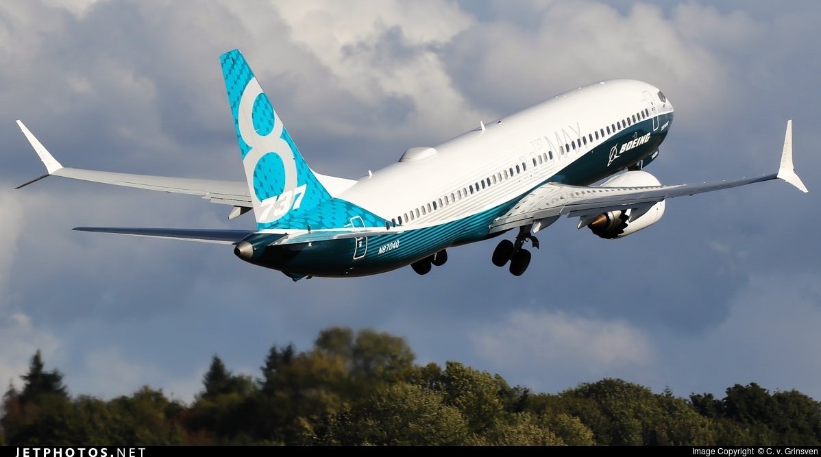
B737 max 8
I came across him a couple of years later and he thanked me for this simple imagery. “Now I get it” he said.
A century after Newton, Jane Austen also knew some basic aero-philosophy: ‘It is a truth universally acknowledged that a wing of infinite span will create no induced drag.’
Such a wing can also make do with no chord and therefore must remain in the imagination, but that is enough mid-lesson faux-philosophy nonsense. There is no hard dividing line between philosophy and the process of understanding anything.
Teaching essentials - what is often wrong with it
Science and scholarship are wonderful things, in the right place, but Principles of Flight as taught to pilots may often short change some essential steps in the understanding process. Just one single link missing from an individual’s chain of logic can thereafter turn a whole area of useful and none too abstruse knowledge into a featureless mass of confusion, best avoided. Too much too soon is a frequent mistake in any teaching; especially the mathematical formulae. To start with, pilots need to understand the basic practical processes involved - using everyday life experience. The sums can come later.
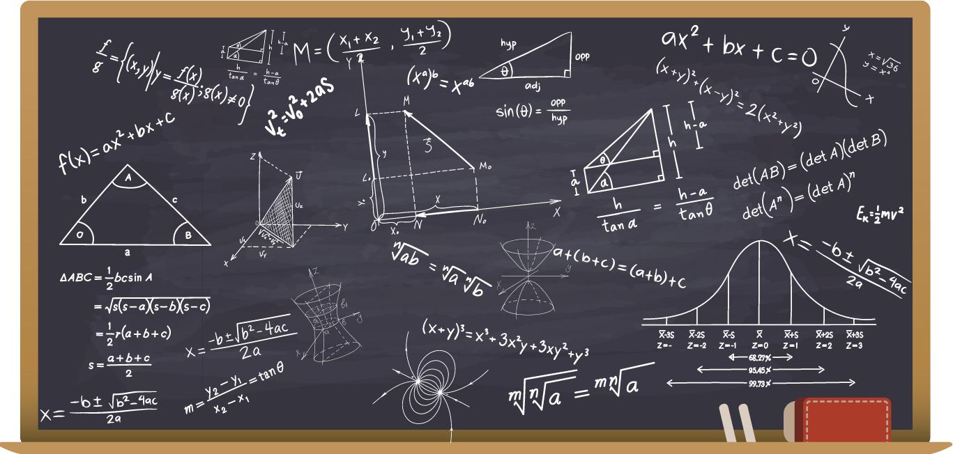
Too complicated for step-by-step teaching
½ϱV2SCL tells you all about lift, but an initial stage of basic understanding does not need such science. A bigger bite of the air should suffice here, and the meaning of CL can wait.
The Wright Brothers understood this, but the perceived urgency of conflict in the air, and the relative novelty of aerodynamic concepts encouraged mysterious snippets of design theory to be chosen as suitable school subjects. Relatively simplistic imagery is better suited to the practical pilot, to begin with.
R.J Mitchell, creator of the Spitfire, said “If anybody ever tells you anything about an aeroplane which is so bloody complicated you can’t understand it, take it from me: it’s all balls.”
We do not need to understand the reasons for his elliptical wing shape in order to manage a take off in a Spitfire, in fact he deliberately played down this topic. “To make space for the guns and wheels” he said. More relevant for a pilot’s introduction would be the importance of educated rudder control, care with the throttle and brake lever, no view over the front, powerful elevators, and so on . . .
A word about this fancy shape

Spitfire
The Spitfire is only included because of R.J.Mitchell’s quoted words about inappropriate teaching for pilots. With its 5.4 aspect ratio the Spitfire resembles simple example A (6) rather than B (2.7), except that the Spitfire’s chord progressively peters out from root to tip, thus reducing the airflow’s abrupt surprise as the end of the wing is reached. In technical terms the lift coefficient along the span is semi-circular; not the graphical rectangles suggested by wing planforms A and B. This principle was familiar to 19th century British researcher Frederick Lanchester of quality car fame, but gained more recognition when propounded by Ludwig Prandtl, active in fluid dynamics and the Focker company during WW1.
A wing shape involving curves is more difficult to build than a rectangular version or straight taper shape (Me.109), which is why there are historically few. But the prototype Spitfire’s performance in 1936 was a surprise, and encouraged production from 1938 to the 1950s, resulting in 20,000 built.
Recent strides, and the subsonic future: Barbie’s plastic - it’s fantastic
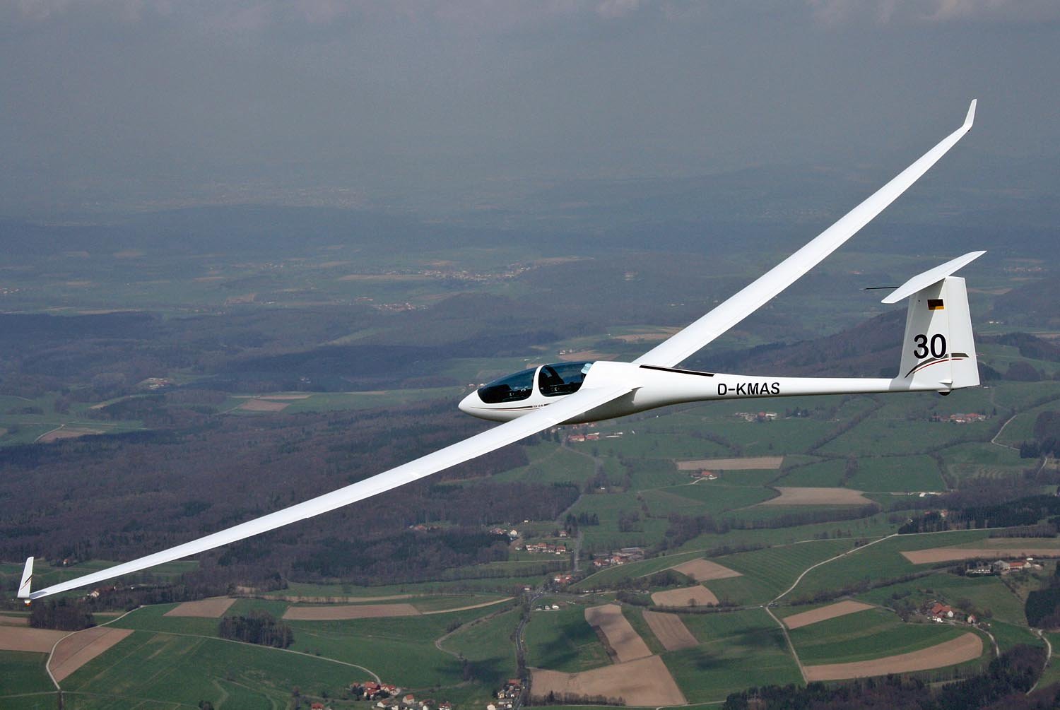
State-of-the-art sailplane
This Alexander Schleicher dual control glider with competition potential benefits from modern, lightweight carbon fibre structure. Such long and narrow wings of 30+ aspect ratio can achieve glide ratios of around 1 in 50. From five and a half thousand feet high you can glide 50 miles in still air conditions, and many have a teeny fold-away engine to avoid the inconvenience of landing out when the soaring is over. Modern long range airliners follow suit, except for the extensive gliding and teeny engine part.

B787 Dreamliner

Airbus A350-9
The Boeing 787 Dreamliner has an aspect ratio of 9.6, visibly bendy wings and much carbon fibre structure. The Airbus 350 long range series has similar aspect ratio wings and this mega-company recently announced a programme of new long range transports - including longer, narrower wings. One upcoming problem of the high aspect ratio airliner trend is parking space. Folding wings, like shipboard aircraft, could be on the cards.
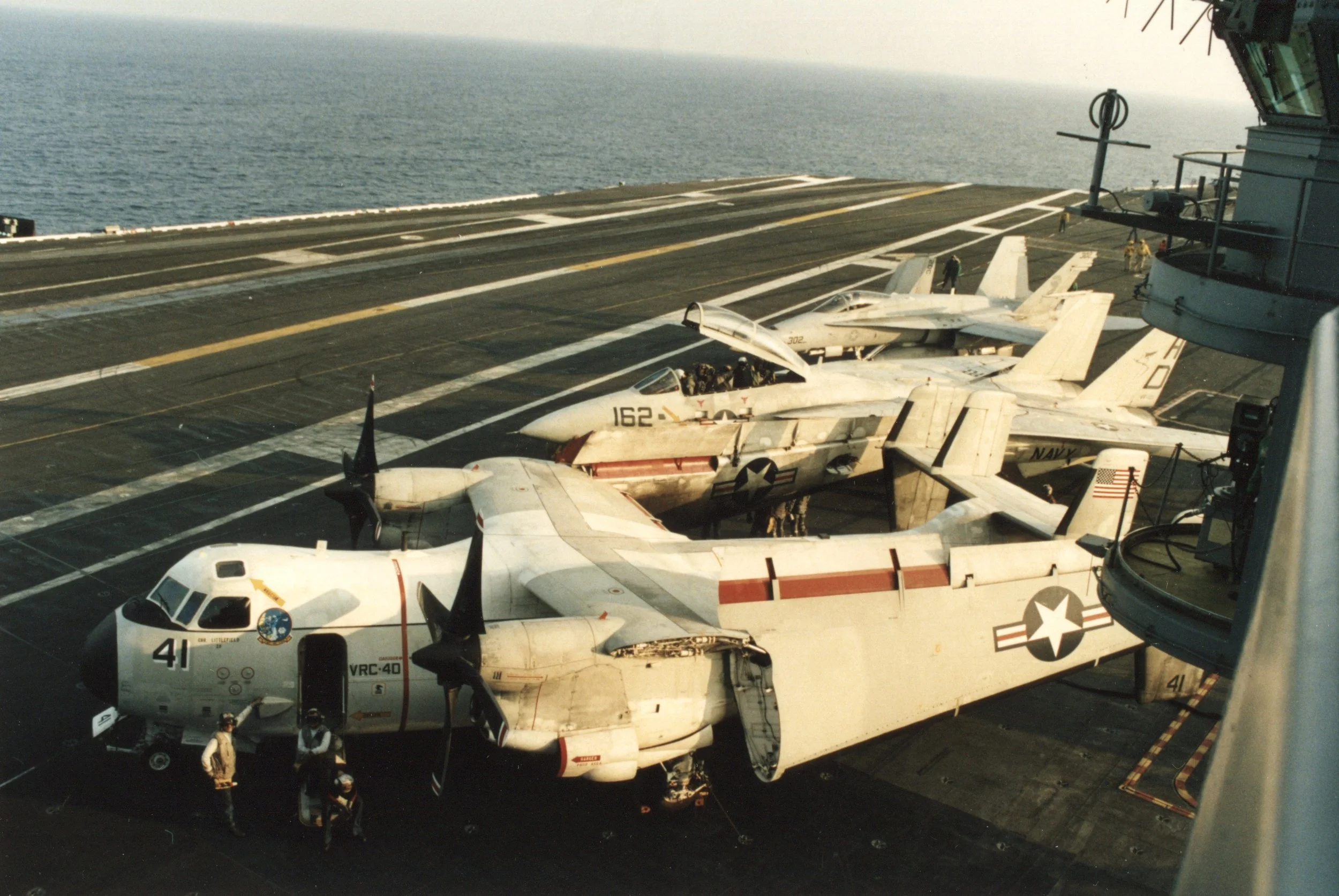
Space-saving parking
Aspect Ratio - Not!

Concorde 1.7, SR71 1.7, Shuttle 2.2
To finish we should look at the fast side of this design coin. As the speed of sound is approached, then significantly exceeded, aerodynamic tradition changes considerably. As airliners go, the Concorde has an extremely low AR example of 1.7 - the same as that of the remarkable SR 71 Blackbird. These machines have completely different tasks from each other, as so does the Space Shuttle - with its apparently more pedestrian aspect ratio of 2.2.
But the Shuttle is not an aircraft, it’s a lifting body device - the wings don’t count. Any similarity with the Concorde’s double delta design is almost coincidental, and one should bear in mind the shuttle’s wide boxy fuselage. This width is included in the wingspan, and the shuttle’s flat underside makes a major contribution to aerodynamic lifting forces: first for reentry drag, then lift for approach and landing. This intriguing NASA research programme is well described in a YouTube video ‘LIFTING BODIES -The Critical Link from X-15 to Space Shuttle’. Glider pilots will enjoy the approach pictures, and responsible transport professionals will be shocked at the lowness of the stabilised final part. Vive le sport!

Steep glideslope (10,000 fpm). HL-10 turning finals for the lakebed